↑top - - - ↑up
Unboxing and Assembling a Magni Robot
This chapter applies to the Silver version of Magni. Two additional versions are planned: Bronze and Gold.
The Magni comes almost ready to run with minimal assembly. Two 12v SLA (Sealed Lead Acid) batteries should be purchased separately. A CR2032 coin cell battery is required for proper operation and must be installed on the back of the main controller board.
An Allen wrench (for M6 bolts) will be included in the shipping box. In addition a small Phillips (cross point) screw driver may be needed for mounting the Raspberry Pi camera.
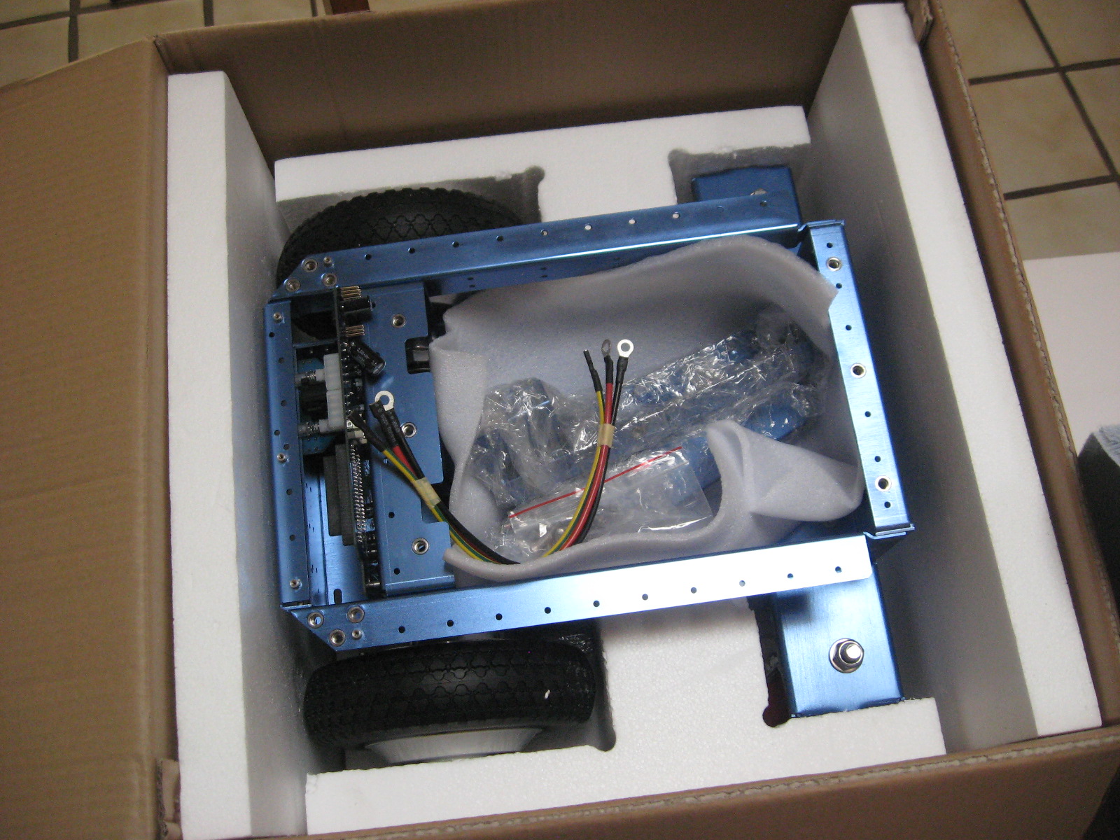
Step 1 - open the box

Inside the box you will find the battery cables, brackets for the cover plate, fasteners, and a cover plate.
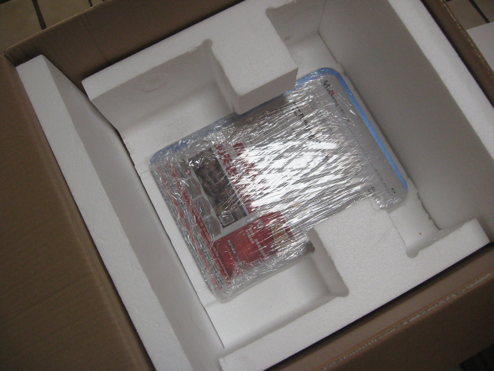
After removing the robot, the cover plate is stored at the bottom of the shipping box.
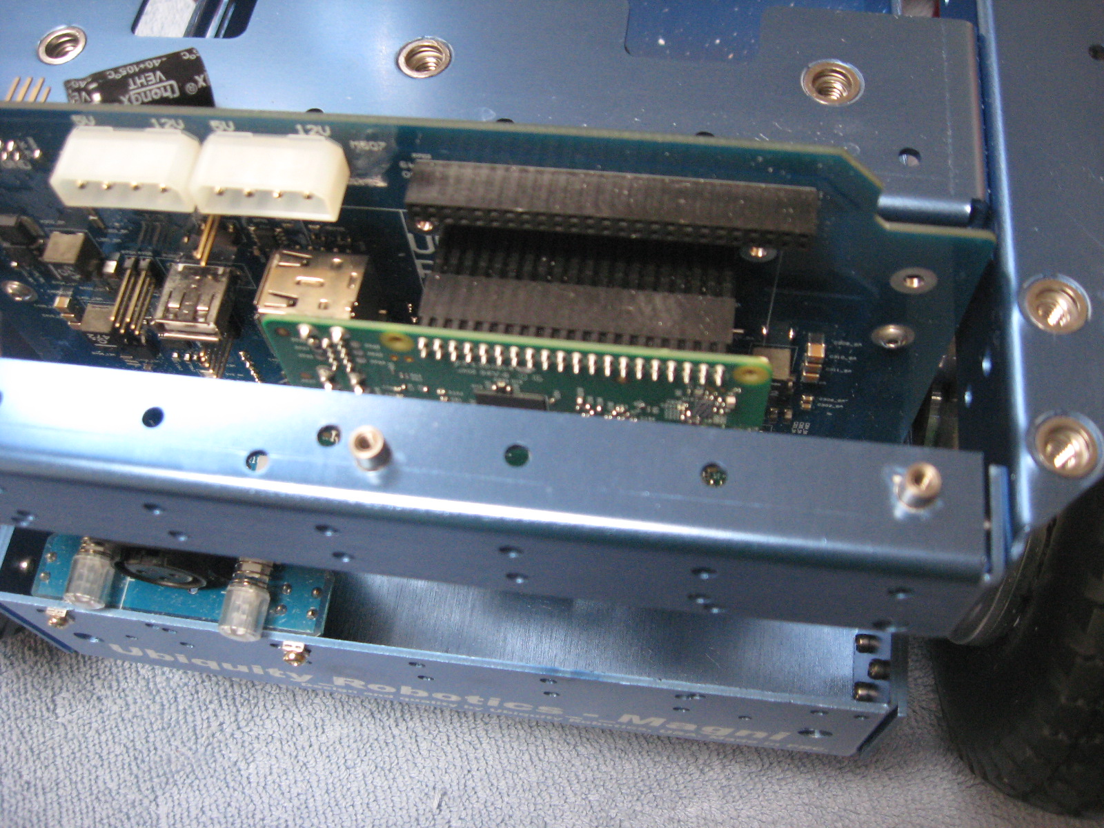
The Raspberry Pi 3 + SD image card can be installed if you have your own image with your own software (Silver and Gold). However a default image may already have been installed in the factory.
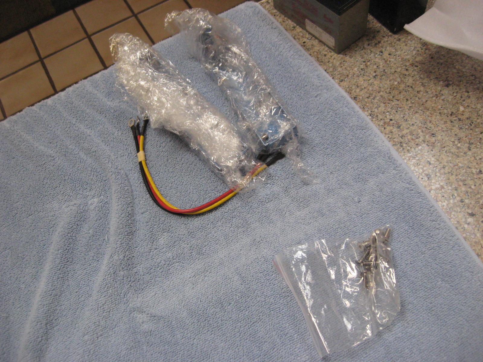
In the small parts bags, you will find fastners and M4 and M2 Allen wrench that fits the included fasteners. The additional sensors (Silver and Gold versions) are wrapped separately.
The front and back brackets can be installed using the brackets require a M4 hex Allen wrench. We suggest an extra long (6 cm). The other included fasteners are M3 (M2 hex wrench) and a small Phillips screwdriver for Raspi Cam attachment. See the detailed section on camera and sensor installation.
Brackets
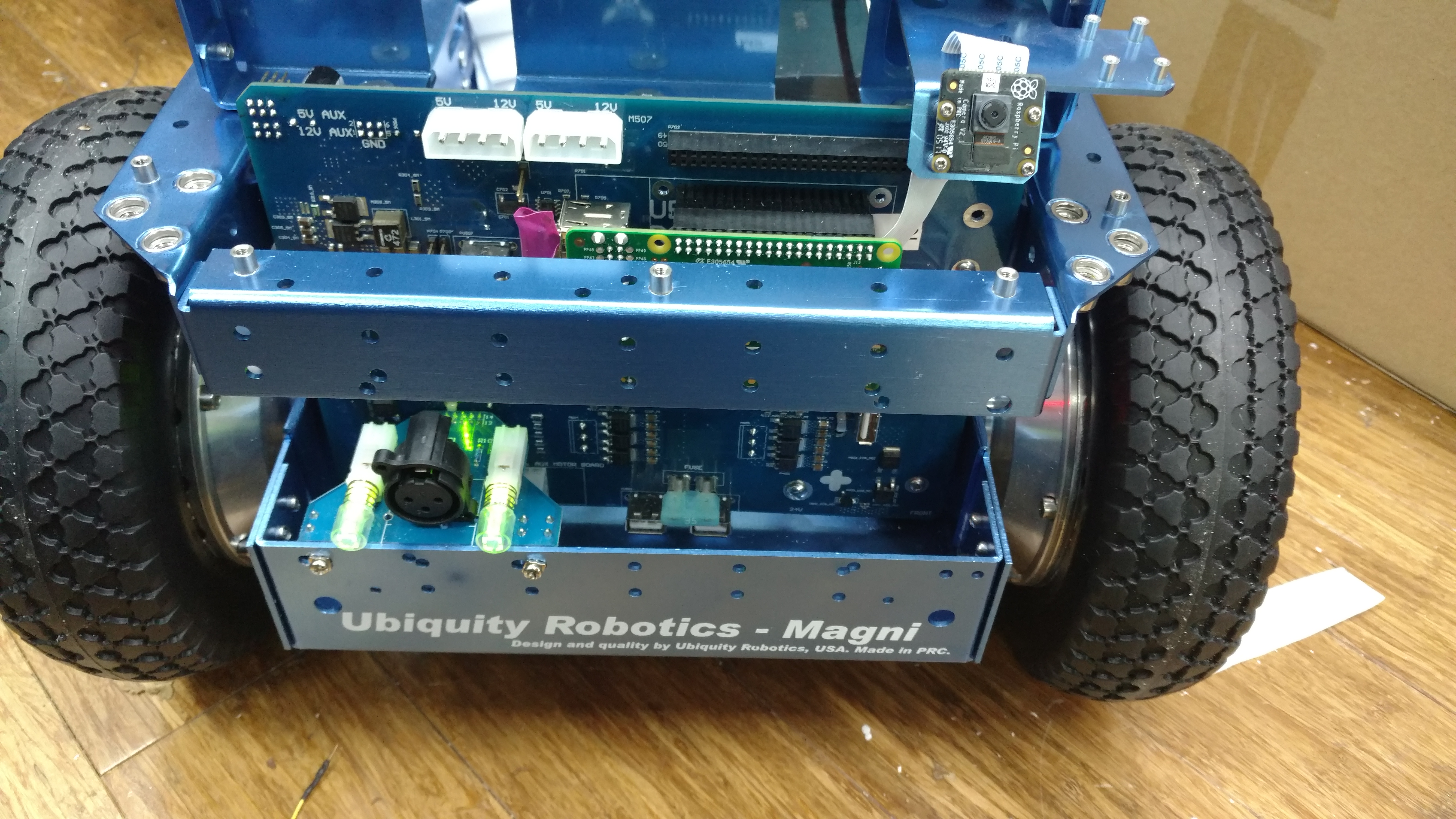
The Front Bracket with Camera is shown above. The system power switch is above the “U” in Ubiquity, and the switch for the power to the wheels is above the “y’. The charging port is between the two switches. Switches light up when on. The ON position is with the switch extended out. Both buttons should be lit.
Do not attempt to operate the robot when the power to the wheels is off. Commands will be stored by the robot and then when power is enabled, the robot may move unexpectedly.
Installing the camera is discussed separately.
The Motors are connected next. This should be done at the factory, If they are detached, there are arrows on the connectors that (-> <-) show the alignment. These connectors are sometimes hard to insert and separate, because it’s hard to grip them.
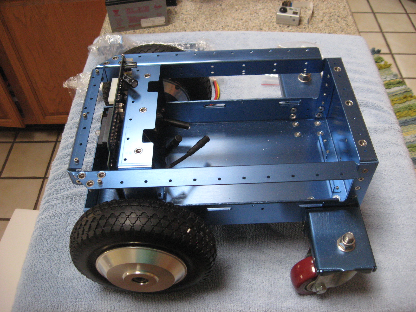
Finally the batteries are connected. The red lead from battery 1 to positive, the black from ground to ground on battery 2, and the yellow to connect the negative of battery 1 to the positive of battery 2. There are cables for both spade type and screw type battery terminals. A 24 volt battery charger is included in the package (Photo not available). The recommended batteries are of the type specified by UB12xxx where xxx specifies Amp Hours. Commonly UB1250, UB1290, or UB12150 are used. Since it is unknown what size and shape the batteries will be it is the user’s responsibility to see they are secured in the chassis by the use of straps or packing material.

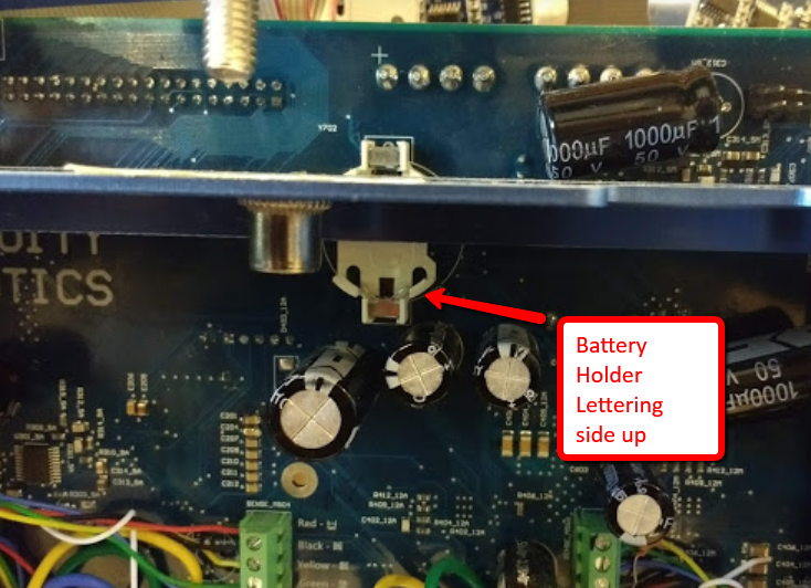
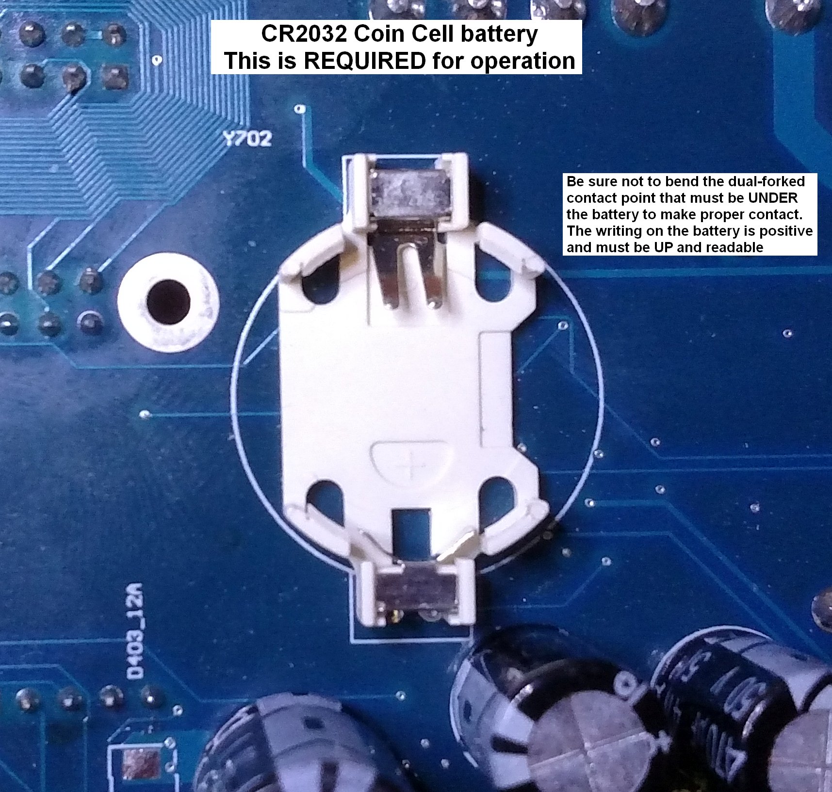
The Real-Time Clock battery
There is also a CR2032 coin cell battery on the back of the circuit board. This provides power to the real-time clock, which is essential. If this battery is not installed, obtain one and install it. Insert the battery with the lettering side up.
A video of the unboxing process is available: Video